VIC - 0893 - Eyarth - My Journey Modelling Eyarth
VIC – 0893 – Layout of the Quarter - MY JOURNEY TO THE MODELLING OF EYARTH – TCH 143
Photos Lesley Allanach
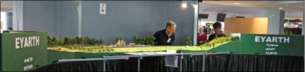
Figure 1 - Above: An overall shot of the layout as we set
up for the AMRA exhibition at Caulfield, Melbourne.
Introduction
– My Interest in Model Railways
I’ve been interested in trains and model trains for most of my life. It’s not that I was given a Thomas the Tank Engine when I was really small or my father passed on his interest – he was certainly not an enthusiast - but I can remember the day when it first started. I’m not sure exactly how old I was but I must have been about ten. Our family were invited to the house of a work colleague of my father’s and his son Paul had some sort of fold down layout in their garage. My elder brother and I were taken to see it and whilst my brother wasn’t really interested, I was transfixed. Paul noted my interest and a short time later I was invited to go train spotting with him to Newcastle Central Station. I was hooked immediately and have never been able to shake it off. As I say, I can’t remember exact dates but the first entry in my train spotting log that I began some time later (yes I know, very sad - but I still have it) was 21/08/71 so it must have been sometime round 1970.
As with so many people, it was these early experiences that formed the basis of my ongoing interest in the hobby. I missed the end of steam by a couple of years so the “romance of steam” is somewhat lost on me I’m afraid. In the 1970’s everything was diesel powered and nearly all of it was blue. I honestly can’t remember even the diesels being green. And while TOPS numbering hadn’t yet been introduced, it followed soon after. So in summary as you will see, I’m fundamentally a “blue diesel man”, so much so that a recent visit to St Pancras Station was quite disappointing. Although it has been stunningly renovated, the high speed trains to the Continent just don’t get me excited in the way that the Peaks and Brush Type 4’s did 40 years ago. The steam devotees amongst our membership who can’t get excited about diesels will probably understand what I’m alluding to.
For much of my youth the focus was on the real thing, chasing trains all round the country, including visits to stations as far apart as Crewe, Edinburgh and the London terminals, as well as loco sheds at Bescot and Toton. It was only later that I moved more into modelling. I had always wanted to build a model railway and I did actually put up some baseboards and lay some track in my parent’s garage at some stage in my teens. It was going to be a GWR branch line terminus, a subject about which I knew nothing – but at the time, pretty much all the layouts in Model Railway Constructor were of that style! That layout didn’t get very far as the four required ingredients for a successful layout (time, space, money, inspiration) were all lacking to some degree and it was soon broken up.
For a long time things stayed the same, although I still often went to exhibitions. I usually came out of them frustrated, wanting to have a go myself but feeling that those required ingredients would not be in place until I retired. For 20 years or more, my only other involvement in the hobby was subscribing to Railway Modeller and doing a little bit of railway research – which I will allude to later. I was the classic armchair modeller.
Break
Through and Inspiration
It was only about 12 years ago that things started to
change. My daughters were getting a bit older so I was starting to get a bit of
time to myself. Having moved to Australia with my employer, my job was also
going quite well so I was starting to have a bit of spare money and there was
always the garage to provide space. I was starting to think that perhaps I
didn’t have to wait until I retired to have a go at railway modelling.
The final required ingredient, inspiration, came courtesy of the BRMA. I went to the AMRA Exhibition in Box Hill, Melbourne, somewhere around 2000, expecting to enjoy the layouts but again come away frustrated over my inability to do anything myself. Whilst there however, I came across the BRMA stand, which was being manned at the time (as it so often is) by a gentleman called Brian F. I was so taken by his friendly attitude and enthusiasm that I signed up for membership on the spot and have never looked back. Through Brian and the BRMA I then met Stuart W., Malcolm D. and many others, who have provided support, inspiration, feedback and materials over the years. This has been invaluable and I thank them all most sincerely.
Abortive
Layouts
Fuelled by this new found inspiration I decided that I
didn’t need to wait until I retired to get started and embarked on the first
layout since my youth. This was another branch line terminus, built with EM
gauge track. It didn’t last long either though, suffering from a multitude of
problems, including lack of ability, lack of planning, bad choice of materials
etc. It was soon broken up like the first layout 25 years before – although I
do still possess the baseboard legs!
Having decided that EM was beyond my current skill levels, I went back to OO for my next layout and built a generic tail-chaser layout on a single baseboard. The idea was to be able to run Australian prototypes as well as British, as I had started building up a stock of Australian locos and rolling stock in addition to my British stock. (Don’t worry though, it has all since been sold). This layout progressed a bit further than the first two but ultimately went the same way as the previous two. I got baseboards made, track laid and ballasted, electrics in place and made good progress on scenery. Eventually however, momentum was also lost on this layout, as there were just too many fundamental mistakes that couldn’t be corrected. In summary, these were caused by trying to squeeze too much into a small layout and there were excessively tight curves and overly steep gradients. So after about 18 months of work, I spent one night stripping out anything I could recover from it and another night with a saw, cutting it up into manageable chunks for the hard rubbish collection. The layout had not been a complete failure however as I had learned much from building it. Some of this involved recognising my mistakes and making sure I didn’t repeat them (Stuart W. was to later say about Eyarth “This is so much better than the last layout its hard to believe it’s been built by the same bloke”!). There were also positives however and in particular, I felt I had come up with a good method for basic contouring and scenery and I had come to appreciate the simplicity of wiring a layout for DCC and had discovered the joy of DCC sound in diesel locomotives.
EYARTH
STATION - A POTTED HISTORY
Eyarth was a small station on the
Denbigh, Ruthin & Corwen
Railway (DR&C) in North Wales. As its name suggests, the DR&C ran from
Denbigh, (where it formed junctions with lines to Rhyl on the North Wales
coastline and to Chester via Mold), through Ruthin to Corwen (where it formed
a junction with the line from Ruabon to Barmouth, via Llangollen). The station
served the nearby village of Llanfair Dyffryn Clwyd.
This part of the line opened on 6 October 1864. Eyarth
station closed to passenger traffic on 2 February 1953 and regular goods
traffic ended on 30 April 1962, with the line formally closing on 1 March 1965.
Like so many others, the DR&C owed its existence to the railway mania that swept Britain in the mid 1800’s and should probably never have been built. It ran through the idyllic Vale of Clwyd in North Wales and whilst the Vale is one of the most beautiful parts of Wales, I doubt it ever had either the population or the industry to justify a full scale railway line. In fact, the original plans really only came to fruition because they attracted the interest of the LNWR and the GWR. The LNWR already controlled the main line along the North Wales Coast from Chester to Holyhead and had access to the new holiday resorts of Rhyl, Prestatyn and Llandudno, with all the holiday traffic that brought. The GWR wanted to get access to that traffic and as they already owned the line through Corwen, they saw the DR&C as the way to get it. To stop the GWR, the LNWR agreed to support the DR&C and eventually took it over and ran it.
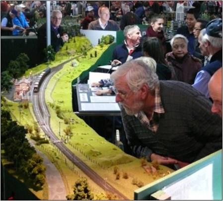
Figure 2 - Right:
This overall shot is looking south towards Nant Clwyd, where the line exits the
scenic section via Eyarth Cutting. In reality, Eyarth Cutting is half a mile or so from the station and I
have plans to build two extension boards to replicate at least part of the run from the station to the
cutting.
For some 100 years, the DR&C had a particularly uneventful existence, firstly as part of the LNWR, then the LMS after the Grouping and finally as part of the Midland Region of BR after nationalisation. There was much agriculture in the Vale and this brought some traffic, as did a few small quarries, timber yards and the like. But they were never substantial. And with such a small population, passenger traffic was never more than six trains a day, even at the height of the railway era. After WWII, business declined on the DR&C and like so many other country branch lines, it was soon ear marked for closure. The portion from Ruthin to Corwen, including Eyarth, closed to passenger traffic in 1953. After that, there were occasional tourist passenger trains (but they wouldn’t have stopped at Eyarth) and limited freight traffic, sometimes no more than one train a day. So not surprisingly, the line closed to all traffic in 1964 and formally closed in 1965. The track was lifted soon after.
As was the case with most of these closed lines, land was soon reclaimed for other uses and in many parts, only a keen eye would be able to pick out where the line ran. Eyarth Station is one of the few exceptions to the rule. The station building survived for some time and is now in private hands, converted to a lovely Bed & Breakfast house. Although much altered and extended, enough of the original building and earthworks survive for it to be clear where the line once ran.
EYARTH
STATION – WHY MIGHT THE LINE HAVE SURVIVED?
The working theory I am running with is pure fantasy,
derived in order to justify having the things I wanted on my layout, including
the locomotives, the types of trains, signage, signalling etc. Here is a
summary of the theory:
As was actually the case, Dr Richard Beeching presented his “Reshaping of British Railways” report on 27 March 1963. This report proposed, amongst other things, wholesale closure of unprofitable branch lines. It sparked an outcry from communities that would lose their rail services, many of which (especially in the case of rural communities) had no other public transport. In 1964 a Labour government was elected under Prime Minister Harold Wilson, having promised during the election campaign to halt the rail closures if elected.
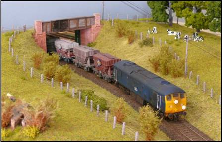
Figure 3 - Right: 24 035 heads south towards Eyarth having passed under the road bridge to Ffynogion farm.
Whereas in reality, they soon back tracked on the election promise, in my version of history they followed through with it, prompted by two major events. Firstly, on 1 November 1964, only days after the election, the world was shaken by a worldwide “oil-crisis”, as Saudi Arabia and other Middle Eastern oil producers were thrown into a major conflict that continued for several years. Soon afterwards, the Daily Mirror published an expose on the previous Transport Minister, Sir Earnest Marples and the conflict of interest that arose from him owning a major construction company – whose main concern was the building of roads. (In actual fact this did not come to public attention until the mid 1970’s). More public outcry ensued and would not go away.
The Government realised that they could no longer allow the move towards road transport and its heavier use of scarce oil resources to continue. Instead they began to steadily increase fuel taxes and other costs of road transport, diverting financial resources towards public transport, including British Rail. They gained considerable political capital by claiming that they had a moral obligation to provide a viable public transport system. This move also distanced the new government from the “Marples Scandal”.
Instead of declining, freight tonnages increased as mass road transport became more and more expensive. As a result of the increased freight activity and the commitment to public transport, lines earmarked for closure or recently closed were re-opened. Specifically, passenger and freight services were reinstated on the DR&C. Freight initiatives such as “Railfreight” were adopted and some rolling stock was re-branded. These services ran alongside traditional trip workings and pick up goods services, for which rolling stock remained in service. Carriage by rail of newspapers, parcels and even cattle continued longer.
However, the move had financial consequences for the Government and money had to be found for investment in the railways. It also changed the dynamics of rail operation. The process of “dieselisation’ was well underway and was therefore completed. But there was limited investment available for new capital stock so solutions had to be found for “first-generation” classes that were perceived to be unreliable (e.g. Class 17) or under powered (Classes 24 & 25). Also, because the local and trip freight services that they were originally intended for had not been lost to road transport, these classes survived longer. Computerisation still came to BR and locomotives were renumbered in accordance with the TOPS system. But there were limited funds available for infrastructure and smaller, less profitable lines such as the DR&C, had to make do with much of their steam age equipment, such as semaphore signalling.
Funding was also obtained by rationalisation of larger stations and selective selling of more valuable land. In the market town of Ruthin, two miles away, the land previously used for the goods yard was sold off to build an industrial estate. To retain some freight handling capacity in the area and to cater for increasing commuting to Denbigh and Chester, Eyarth station received something of an upgrade, with a hard standing area added to the siding, additional security and the provision of basic parking facilities. The previously single track road from the station to the main Ruthin - Wrexham road was also widened. The rest is history..... well, actually fantasy!
Background
to Eyarth
After cutting up the tail-chaser, I then embarked on my
fourth and current layout, Eyarth. To understand why
I picked this location to model, I have to go back a bit to the early 1990’s
when I was still living in the UK. At the time, I was living and working in
North Wales and as I have always done, I began poking around to find out about
the railway lines of the area, both those still open and those now closed.
This is how I came across two former lines, the Vale of Clwyd Railway and the DR&C. As their names suggest, they ran through the Vale of Clwyd, from Rhyl, to Denbigh and from Denbigh through Ruthin to Corwen respectively. The Vale of Clwyd is a most beautiful part of the world and the various stations along the lines were just crying out to be modelled, a result of both their surroundings and their varying but always manageable size. To this day, I am amazed that more models from these and other lines in North Wales have not appeared in the model press. The area boasts stations as small as wooden platform halts, right through to an LMS/GWR junction with an engine shed (at Corwen).
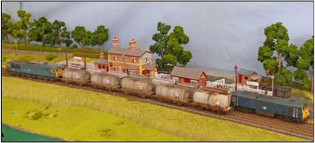
Figure 4 - Above: Trains passing in the loop. 24 035 head south with a cement train for the cement works at Pen-y-ffordd, while 56 022 waits in the loop with oil empties.
I was particularly taken by Eyarth, a single platform/single siding station, situated on a long sweeping curve, just south of Ruthin that was set in beautiful country side and which still partially exists (the old station building is now part of a lovely B&B house). I decided that one day I would model it because it had everything I was looking for including a manageable size but some operational interest, a beautiful location, natural scenic breaks and some remaining infrastructure. I used what little spare time I had at that stage to build up a library of information about Eyarth. This included buying books, sourcing old photographs of the station in use, taking photographs of the remaining infrastructure and spending many hours in the Clwyd Record Office, wading through old LNWR documents to find plans and drawings of the station and surrounding area. This archive has been of invaluable use to me during the planning and building stages of Eyarth.
Eyarth – the Layout
Eyarth is an attempt to recreate
the real Eyarth Station as faithfully as possible
given the limitations of available space and of my archive material. It is an
end-to-end (or “fiddle yard to fiddle yard”) layout. There are moveable storage
cassettes at each end and the single line runs from them to a passing loop in
the centre of the layout. There is also one siding that allows limited shunting
activity. The idea is that trains are driven from each fiddle yard into the
loop, where they pass and are then driven off scene to the other fiddle yard.
Each cassette generally holds three trains and once all trains on a cassette
have been driven to the opposite end of the layout, cassettes are turned around
and trains are driven back to their original location.
The layout is built as a quarter circle with a radius of approximately 4.2 metres. There were two main reasons for adopting this configuration:
The layout was built in my 5m x 5m garage. A straight layout would have given a maximum length of 5m but a quarter circle gives about 7.5m run length in the same space. The real Eyarth was laid on a gentle curve and I wanted to replicate that. A quarter circle gives a much gentler curve than a full or half circle.
From time to time, I have had pangs of regret over this design. Had I built it as a full circle I could have just watched the trains go by, an urge I have every now and then. More importantly, at exhibitions an absolute minimum of three operators is needed (one to work each fiddle yard and one to change points and signals). Realistically however, in order to keep trains moving as much as possible for the public, a team of 6 is needed. That’s a lot for such a small layout. Having said all of that, I have had quite a few complements about the design and how it tends to draw you in to the scene – not that this was in any way envisioned by me at the start! These comments have come from such diverse sources as Ian F. and John P. So I think I’m happy overall.
In order to make the layout portable, it is constructed from 7 separate boards of approximately 1 metre in length. The boards are not rectangular but are parallelograms, with the join between each board creating an angle of 15 degrees (hopefully the photographs will explain it better). Of the 7 boards, two are for the fiddle yards/cassettes and 5 are scenic.
Due to space constraints, cassette lengths are limited to 1 metre. Although this limits train length to locomotive and between 4 and 7 wagons depending on their wheelbase, it also limits the length of the required passing loop and results in the scenic section having good proportions relative to the loop and the single track approaches at each end. So whilst I do admit that a Class 56 pulling only 5 oil tankers does look rather odd, I am happy overall with the outcome.
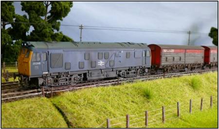
Figure 5 - Below: 25 245 enters the loop with a train of Railfreight branded vans. I have assumed that this sort of traffic somehow persisted in the area and helped keep the line alive.
The scenic breaks at each end of the layout are based on structures that actually existed. At the northern (Ruthin) end, the line enters the scenic section under the bridge that carried the road to Ffynogion Farm. At the southern (Nant Clwyd) end, it enters through Eyarth Cutting. In both cases however (and particularly in the case of Eyarth Cutting) these features were much further away from the station than I have depicted. This is a compromise that I have no option but to accept.
I have already mentioned that I am conscious that the layout has less movement of trains than a circular layout. I have therefore also built information boards with photographs of the real line, history and background details to try and maintain some interest for viewers between the passing of trains. This board is integrated into the overall layout.
Eyarth Construction
I’m really not sure how to condense more than 4 years of work into a few paragraphs of text. I am also conscious that members probably don’t just want to read a list of where I bought all the bits and pieces from – or even worse, read comments such as “track was ballasted in the usual way”. So instead, I will limit my comments to a few areas that have been the subject of most of the interest I’ve had from viewers of the layout.
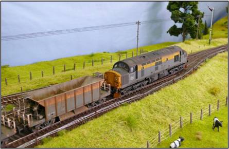
Figure 6 - Right: Having received the token for the
section between Eyarth and Nant Clwyd and having the
all clear from the starter signal, 37 035 exits the loop with its ballast
empties, heading for one of the quarries further down the line to re-fill.
If you would however like a blow by blow account of my material sources and construction techniques, I would refer you to the web site run by fellow BRMA member Martin K., where I have several pages and quite a few photographs. The address is:
www.modelrailmusings@weebly.com
DCC
Firstly, I’d like to touch on the “Hot Topic” that is DCC.
Let me say first of all that, like all modelling subjects, I understand there
are quite different views on the advantages and disadvantages of DCC and I
respect them all. I don’t believe there’s a right or wrong. DCC has some
advantages and disadvantages over traditional DC control that may or may not
apply to an individual, depending on size of layout, existing layout or new
build, number of locos etc. I think you just have to weigh up the pros and cons
and come to a decision based on your own personal circumstances, in the same
way as you might decide between steam and diesel or between LMS and LNER. In my
case, starting on a new layout I could start with a clean page and didn’t have
to worry about undoing anything I’d already done. So I must admit that being
neither an expert in electrics generally nor soldering
specifically, the concept of simple wiring appealed to me. As I have explained
on the web site, I didn’t quite get down to the “one red wire, one black wire”
situation but even on my simple layout, I still found that my wiring was
simpler than, say, DC cab control would have been. I know that there’s every
possibility that one of the resident BRMA electrics experts could have
replicated the simplicity in DC but importantly for me, the inherent simplicity
of DCC meant I could do the electrics myself.
Having said that, the real clincher for me was DCC sound. Once again, I understand that the availability of DC sound is expanding but when I made my decision, both the quality and ease of fitting of “plug and play” DCC sound was so high that I just had to have it. My personal view is that the effectiveness of replicating the real sound of a particular class of locomotive is greater with diesels than steam. So once again, I feel that I was at an advantage to some. I remember in my youth that we could tell what class of loco was approaching before we could see it because so many of the diesels had their own distinctive sound. With a Howe’s sound chip in, say, a class 20, 25 or 55, I can do the same on my layout (although in the case of the class 55 I wish I could fit a bigger speaker!).
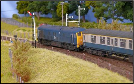
Figure 7 - Right: 24
023 heads a passenger train north to Ruthin and Denbigh. In reality, Eyarth was never a token exchange point and the loop was
not protected by a full set of signals, so the ones here are just a bit of
fantasy. The unusual format of the two home signals in the background is based on
real signals near Abergele on the North Wales Coast main line. Signals are made from Model Signal
Engineering parts and are operational. Power is provided by Tortoise point
motor, with a Modratec clutch mechanism between motor and signal to prevent
excessive throw
Fitting of DCC sound chips is not without its challenges though. I know you can now buy locos with factory fitted DCC sound but the range is still limited and if you want to go fully to DCC sound, you have to be ready to attack with your screwdriver to open up your locos and in some cases, attack with your mini-drill to make room for a speaker. It amazes me that with the popularity of DCC sound, even some of the latest releases (such as the Heljan Class 128) don’t have specific provision in the chassis for a speaker and even worse, sometimes there’s little room at all. I can tell you that the first time I took to the moulded interior seating of my Class 105 DMU with a Dremell and cut out a hole to make the speaker a little less obtrusive, I was very nervous!
The cost of DCC sound is also an issue as it roughly doubles the cost of a locomotive. Fortunately I have a smaller loco stud than some of my BRMA colleagues with large layouts. But even my 20 or so locos (yes I have more than 20 locos for a single line branch layout with one siding) have ended up requiring a significant investment. It’s a matter of choice whether you can justify that cost and I feel that I was lucky to be in a position to do so.
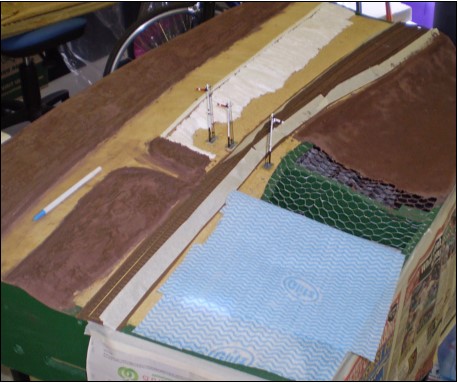
Figure 8 - Left: An
early shot of board #7, showing basic construction techniques. Where ground
level is above track level, contours are built up with expanded polystyrene,
which is then covered with a layer of cornice cement that has been coloured
with cement cement colouring. Where ground levels are below
track level, contours are formed from chicken wire, which is then covered in
kitchen cloths that have been soaked in the coloured cornice cement.
So I have gone down the DCC route and have no regrets. I use the Digitrax system for no other reason than because the Branchline Model Shop is a Digitrax dealer and I felt that it would be good to have someone nearby who could offer technical support. Overall, I’m pretty happy with that choice.
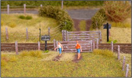
Figure 9 - Left: This is board #7 when finished. Hopefully it shows how the above construction techniques turn out..
The
Station Building
I would also like to make a few comments about the station building. This is the only significant structure on the layout and I realised pretty early on that the quality of the representation of the station building was going to be the measure of how successfully I had transformed the layout from a generic country branch to a model of Eyarth. So the building got lots of attention – somewhere in the region of 200-250 hours!
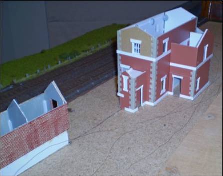
Figure 10 - Right: An
early shot of the two major structures, the station building and goods shed,
under construction. This may illustrate some of the construction techniques
described in the text, in particular the sandwich format of the walls. At that
time, the station building walls were
only held together with Blue-tack!
Obviously, no readymade model of the station exists, so I had to scratch build my own – something I’d never done before. I was fortunate however to have acquired several drawings (all plan views) of the building during my visits to the Clwyd Record Office. One of the best ones was copied and reduced to scale size on A3 paper. From this I drew up the elevations using a number of photographs and counting of the brick courses. This required me to use my long dormant schoolboy Tech Drawing skills from many years ago, which was fun but I’m sure I should really have taken the plunge and used CAD! There were some areas where I didn’t have any photographic evidence but the drawing process allowed me to make decisions (guesses) on how it might have looked in advance of the actual build. These drawings became the plans for the build process.
Over the years I had found a few good articles in model railway magazines on building construction and my construction techniques were greatly influenced by these. Generally speaking, the walls are made from a three-layer sandwich of plasticard, the outer layer being Slater’s embossed brick sheets and the others being 1mm plain plasticard. The three layer concept adds strength and rigidity to the walls and according to one of the articles I read, produces a warp resistant structure in the same way as 3-ply plywood. This is also why I have not generally mixed layers of card with layers of plasticard, as they react differently to changes in temperature and humidity. It made sense to me anyway! The multi-layer concept also has the advantage of adding depth to the window openings.
One of the distinctive features of the stations on the DR&C is the use of quoins and so these had to be incorporated into my model. Plastic quoins are available from Wills but they seem to be intended as overlays and I thought that would make them too prominent. Instead I cut back the embossed brick plasticard sheets to fit the profile of the quoins so that they would look more integral to the wall. This proved quite time consuming and fiddly and ended up with the use of quite a bit of filler but has, I hope, achieved the desired effect.
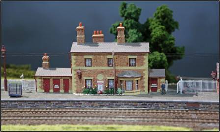
Figure 11 - Left: A later shot of the finished building. Although its from a different angle, hopefully it will show the final result of the various techniques described. Don’t look too closely at the wonky rear chimney stack though!
Corners that did not have quoins also got close attention as I tried to make sure that the plain edges of the plasticard that had been cut were not showing. A number of steps were involved:
I cut the embossed plasticard sheets with a course or two to spare at the top and the bottom so that I could make sure that courses aligned with those on adjacent walls. Excess courses were trimmed off afterwards.
The edges of the embossed sheets were bevelled, trying to get them to 45 degrees, so that when they are stuck together, the plain edges do not show. This is more easily done with thin Slaters embossed plasticard than with thicker Wills sheets.
Steps 1 and
2 were not 100% effective and I still found that there were some gaps between
the adjacent outer sheets when I test fitted walls together. This was largely
rectified by step 3 below.
When gluing
walls together, I used a generous (but not excessive) amount of plastic cement.
This softened the thin bevelled edges slightly. Before the plastic had
completely hardened again, I used a small needle file to file out each cement
course so that it flowed around the corner. This also tended to have the effect
of squeezing the two sheets together at the bevelled edge and eliminating any
small gaps. Although not perfect, I am happy with the overall outcome of this
process.
The style of
windows at Eyarth and other DR&C stations was
quite distinctive and I couldn’t find anything readymade that looked the part.
So windows are individually made from Evergreen plastic strips of various
thicknesses. These are mounted onto a small backing piece of plasticard, which has an opening in it the same size as the
opening in the wall. Doors were made in a similar fashion. It turned out to be
a very fiddly job and if I had my time again, I would look into the cost of
having some bespoke windows made professionally!
All
brickwork was painted after the main walls were assembled to make the shell of
the building. First, an all over coat of mortise coloured paint was applied.
Then a second coat of brick coloured paint was “dry brushed” over the mortise
coat. That way, the embossed brick surfaces are painted but paint did not flow
into the mortise joints, leaving the original colour showing. Finally,
individual bricks were picked out in various different brick shades.
Chimneys are
made in a similar way to main walls but on a smaller scale and I could really
only use a two layer sandwich. Roofs are also a two layer sandwich, overlayed
with self adhesive tiles from York Modelmaking. This is a move away from my
principle of not mixing plastic and card but was forced on me by the limited
size of Wills embossed roof tile sheets and my dissatisfaction with the profile
of the larger Slaters embossed tile sheets. I have been very impressed with the
York Modelling tiles. They are easy to cut and remove the backing and adhesion
is very good. A little bit of care is needed to get rows completely straight
but any minor deviations are not apparent from normal viewing distances.
Flashing around chimneys is just cut from a sheet of grey photocopy paper that
has been printed with a darker block of grey. I have used Wills and Ratio
building detailing packs for gutters, chimney pots, downpipes and decorative
chimney brickwork. The downpipes look to me to be a bit over scale but a
reasonable compromise in terms of cost and availability versus accuracy.
Fences & Telegraph Poles
These are
the two items that have been the subject of most questions when people have
viewed the layout. So I thought I might explain how I made them. With respect
to fences, I have often been asked why I don’t just buy them – especially by my
wife. My answer is that bought plastic ones always look like bought plastic
ones! Instead mine are made from match sticks (bought from a $2 shop). The
sticks are cut in half and sharpened to a point at one end. Four holes are
drilled with a pin vice and the posts are then primed grey and finally dry
brushed in brown. Single strands of wire are unwound from multi-strand
electrical wire and the posts are threaded onto the wires before being put in
place. Posts are then glued into small pre-drilled holes and left to dry. Once
the glue is dry, the wires are tensioned as much as possible from either end.
All of this takes hours, of course, but apart from the painting, this can
mainly be done whilst watching a game of footy or cricket on the TV. Perhaps
you now know however, why my wife thinks I should just buy them!
Telegraph
poles are Ratio items. They are plastic and so are a bit too flexible. Perhaps
handmade ones with brass poles would have been better. But I liked the level of
detail that the Ratio poles have, so have stuck with them. The “wires” between
each pole are actually Oingo-boingo wire, a soft
stretchable plastic. It was bought from the on-line modellers shop, “Modeller’s
Warehouse”. After the poles had been painted, they were placed into pre-drilled
holes on a long piece of wood. The holes in the wood were closer than I
intended to place the poles on the layout. The oingo boingo wire was then glued to the poles, with no tension,
allowing for some sag. I decided it would have been too difficult to wire them
up once they were on the layout. When the poles were placed on the layout, the
wire stretched out to give a nice uniform finish. Prototypically, the wire
should still have some sag in it but after experimenting I found it very
difficult to get the same amount of sag in each wire or to stop the wires
getting tangled. Hence the taught nature of the wires on the layout.
Summary and Where to From Here
Eyarth took
a total of 4 ½ years to build. There were periods when nothing got done but the
last 8 months were pretty intense, getting it ready for the AMRA exhibition in
Melbourne in August 2013 - so much so that even I was relieved when it was
finished. Even though I am perhaps my own worst critic and know that there were
a hundred things I could have done better, I was reasonably happy with the
outcome. I was also very happy with its showing at the AMRA exhibition, where I
received many more positive comments than negative and even picked up two
awards. In short, the weekend was a lifetime ambition realised. So thank you
again to everyone who has helped, especially to Malcolm D., who as well as
providing lots of ideas, suggested solutions and physical help when I couldn’t
manage on my own, has become chief operator. A massive thank
you also to my wife Lesley, who has not only tolerated my obsession but has
actually joined in. Victorian members may have seen her operating points
and signals at the AMRA Exhibition.
As to where
from here, despite saying that the layout is finished, we all know they never
are. I have already started building two more baseboards so I can have a
longer, more prototypical run from the station to Eyarth
Cutting, including bridges over a road and a river. Problem is, with those
extra boards the layout will be too big to set up in my garage. Any ideas
Malcolm?