Copyright (C) 2016-2018 British Railway Modellers of Australia Inc.
Harrington Street - Video August 2021A sequence of train departures from Harrington Street |
 1 Harrington Street A P4 layout... |
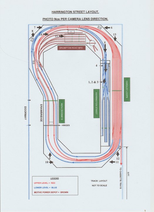 2 Track Layout Plan indicating the locations around the layout from which the photographs were taken. |
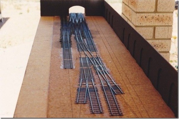 3 Photo 1: ’Small beginnings’ circa 1990. The Harrington Street layout is a project in the making. It was originally conceived in 1988 (based on the drawings of Cyril Freezer in Railway Modeller magazine), as an out and home layout between a small urban terminus and an extensive fiddle yard. As my interests are the Southern Region of BR circa 1955-65 plus some childhood memories of the LMR and WR, I wanted a sort of urbanised Somerset & Dorset line and, as a result, the West London Line - with traffic to and from Clapham Junction (SR) in the south, and Acton (WR) and Willesden (LMR) in the north - looked the best choice for the variety I wanted. |
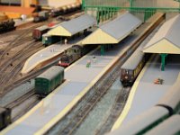
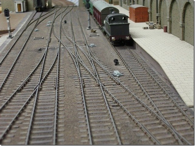 4 Photo 2: The same view in 1995, looking theoretically west. The station proper comprises four platform roads and a parcels bay serving the local post office - all still unfinished! Operation involves the control of arriving and departing passenger and mail trains, constant light-engine movements to and from the station plus a station pilot attaching vans to departures and detaching vans from arrivals. |
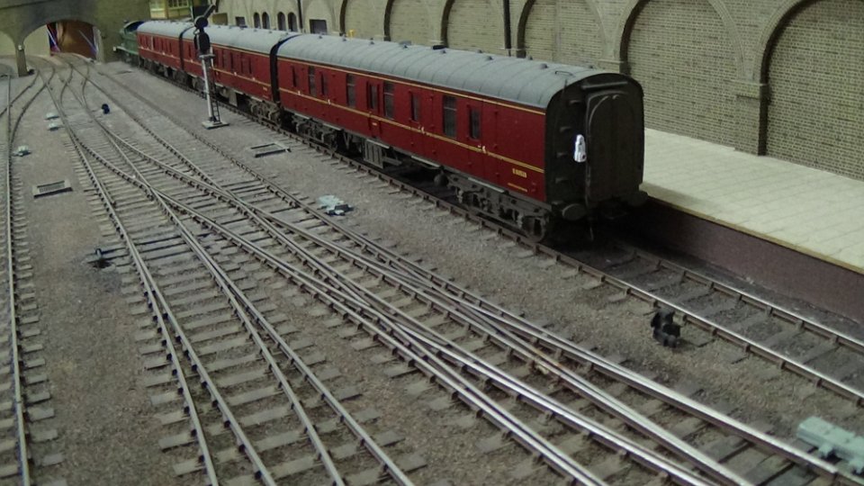 5 Photo 3: The Parcels Bay with BR Mk1 BGs (plus trapped Collett Goods engine!). Some interesting shunting is involved between the parcels bay and the platforms because, either way, the pilot must run around its vans. |
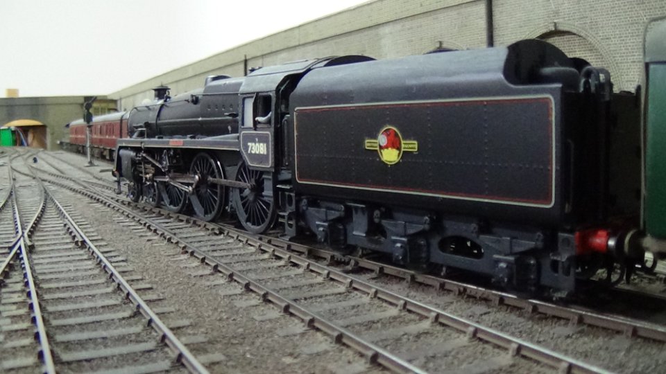
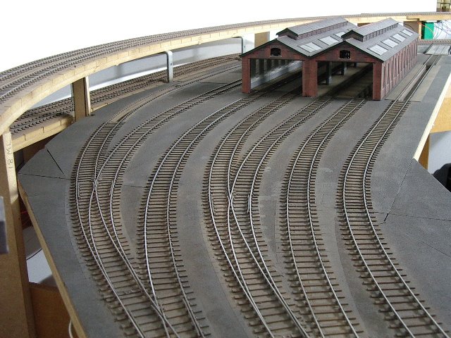
 6 Photo 4: Harrington Street terminus looking theoretically east from the road bridge. (The closed arches were hand cut). Trackwork is to 4mm/ft scale,18.83mm gauge and comprises code 75 steel bullhead rail glued to either ply or ABS sleepers via ABS chairs, no rivets have been employed anywhere on the layout; the only soldering being to 0.6mm copper-clad bonding strips in strategic places within pointwork. All trackwork is laid onto a 3mm cork tile base glued to the baseboard surface. |
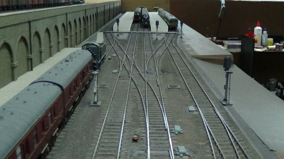
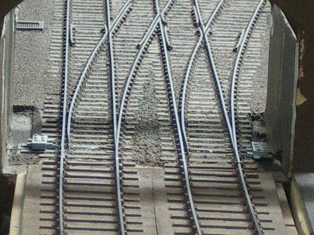 7 Photo 5: The entrance to Harrington Street. Turnout control is achieved via Studiolith turnout operating units (TOU’s) activated from Tortoise slow action point motors. Common crossing polarity being controlled via one of two internal switches. Harrington Street’s approaches comprise 4-B8 and 4-B7 turnouts plus a B7 double slip, all arranged as crossovers, thus, only one panel switch is necessary per crossover. Each cross-wired DPDT panel switch is wired to throw both motors simultaneously. |
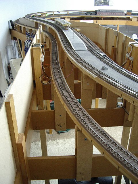
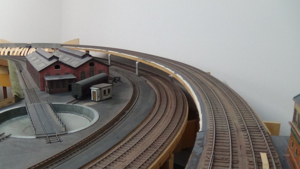 8 Photo 6: Overlooking the terminus arrival/departure roads diving under the main lines above, with Brompton Road MPD to the left. Subsequent extensions to the railway have involved a 180 degree curve of 4ft-6in minimum radius on level grade, then splitting, with the down line passing under the continuous main line on the other side of the room - Phase 2. |
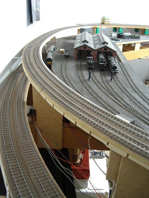 9 Photo 7: Looking in the opposite direction with the MPD and lower tracks re-emerging from under the main lines. |
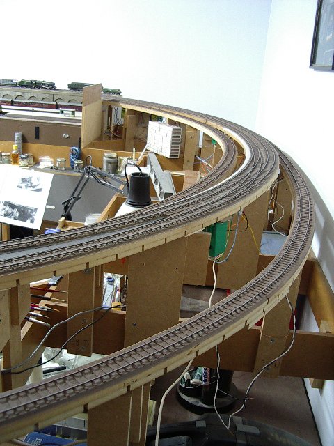
 10 Photo 8: Following on we have the MPD exit far left, main lines centre about to enter Elmwood Park Station and splitting lower tracks again to our right. The crossover sets light engines from the MPD exit ‘right-road’ to the terminus. |
 11 Photo 9: Looking in the opposite direction to Photo 8 we have the main lines this side of an embryonic Elmwood Park Station and the lower split terminus lines either side. |
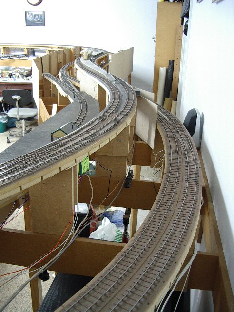
 12 Photo 10: Looking to our right, we see the ex-terminus lines climbing (on the left) and falling (on the right) either side of the main continuous running lines. After splitting, both lines assume a gradient of 1:68 and, again, curving through 180 degrees at 4ft-6in radius, the outside lines enter passing loops (Eardley Junction) behind Harrington Street station - Phase 3. |
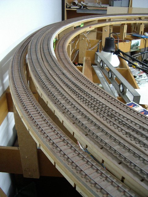 13 Photo 11: And moving to the next corner we get a view in the opposite direction. |
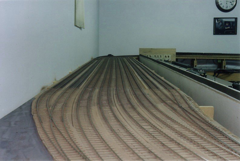
 14 Photo 12a - before traffic |
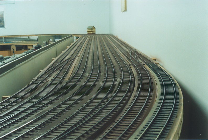
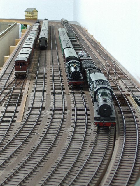 15 Photo 12b: Facing to our right reveals the entry/exit lines of Eardley Loops Traffic in operation |
 16 Photo 13a Before being loaded with rolling stock. |
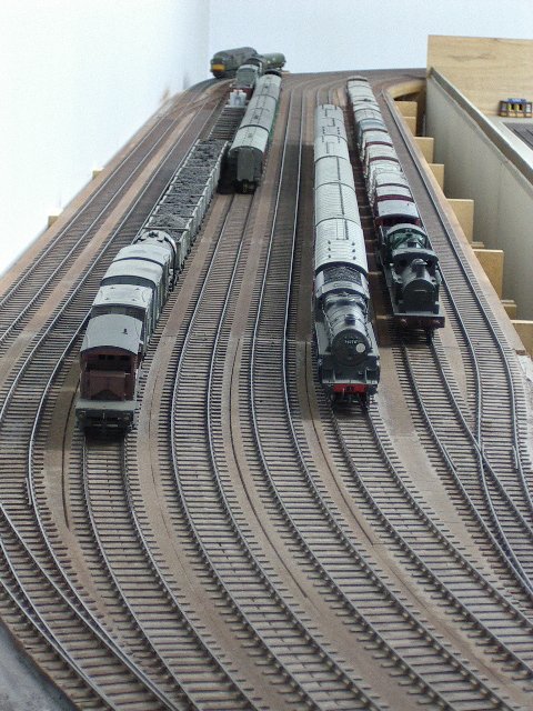 17 Photo 13b: We’ve travelled full circle now looking back at Eardley Loops from the opposite end. |
 18 Photo 14: A view of Brompton Road MPD when new in 2005. |
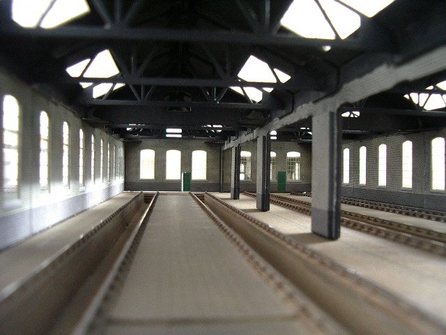 19 Photo 15: And a peek inside before benches and lockers were installed. Stores and mess rooms at rear |
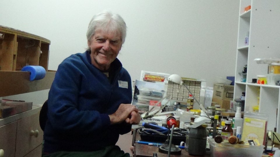 20 Photo 16: Myself at my ‘Works’ - (Ashford at this juncture!). |
Harrington Street PrecisA description of Harrington Street
|